DC motors are used for various applications in Domestic, commercial and Industrial area. But for different application need to operate the dc motor at different speed to get the best outcomes. Therefore Speed control of DC Motor is very essential.
From above equation we can conclude that the factors affecting the speed of a dc motor as follows:
1) The speed is inversely proportional to flux (Φ).
2) Speed is directly proportional to armature voltage (Va).
3) Speed is directly proportional to applied voltage (V).
That means we can control the speed of DC motor using adjustment of above parameters.
Speed Control of DC Shunt Motor
DC shunt motor speed can be controlled by two method which is,
a) Flux control method and
b) Rheostat control method.
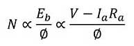
Flux Control method for Speed Control
The arrangement for speed control of a dc shunt motor using the flux control technique is shown in figure. For change speed, we have to change the flux.
This can be achieved by changing the field current flowing through shunt field winding. The field current can be changed by changing the value of rheostat ‘R’ connected in series with the shunt field winding as shown in figure.
We know that current decrease in the field winding then flux also decreases and vice versa. Initially at the time of starting we need to run the motor slowly.
That is possible when flux should be maximum. To obtain maximum flux, the field current should be maximum. For this the value of rheostat ‘R’ should be minimum.
Therefore at the time of starting rheostat set at point A and change position of rheostat from point A to point B. At point B rheostat connect maximum resistance and current flowing through shunt field winding is low, this low current cause less production of flux.
We know that speed of dc motor is inversely proportional to the flux. Therefore speed of dc motor increase from point A to Point B.
This method of speed control is used for increases speed above the rated speed.
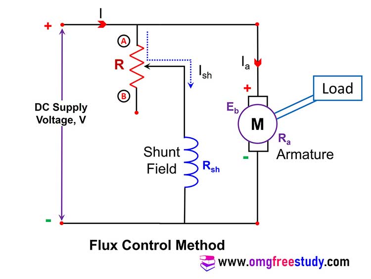
Rheostatic Control Technique
The set up for the armature resistance technique or rheostatic control technique of speed control for DC shunt motor is shown in fig. A rheostat R is connected in series with the armature winding at point A and B. By varying the value of ‘R’, we can vary the armature voltage ‘Va’ that appears across the armature winding.
We know that the speed N is directly proportional to armature voltage, therefore it is possible to change the speed by changing the value of rheostat ‘R’. When sliding contact at point ‘A’ zero resistance will added in the armature circuit, that’s mean no change in value of armature voltage and also in speed.
If sliding contact move from point ‘A’ to point ‘B’ then the rheostat resistance added in armature circuit this cause decrease in value of armature voltage ‘Va’. Due to reduction in ‘Va’, the speed of the motor will be decreases. Speed will be normal rated at point ‘A’ and minimum when the sliding contact of the rheostat is at point ‘B’. This method of speed control is used for speed control bellow the rated speed.
Speed Control of DC Series Motor:
Question: Explain with suitable diagrams flux control method and armature control method for speed control of D.C. series motor?
Flux Control for DC Series Motors:
Flux can be control by following methods
a) Field Diverter method
b) Armature Diverter Method
c) Tapped Field Method
Question: Describe the flux control method using field diverter method for speed control of dc series motor with the help of neat diagram.
We know that speed is inversely proportional to the flux, on this basis we can control the speed of dc machine by changing the value of flux. There are some important method for this type of speed control given bellow.
Field Diverter Method:
The field diverter method circuit arrangement shown in figure. In this method a variable resistor or rheostat ‘R’ is connected across the field winding. This resistor is also called as the field diverter. Therefore this method name as field diverter method.
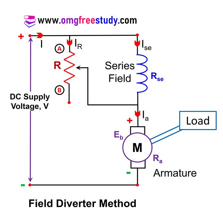
The field diverter connected in parallel with the field winding provides a parallel path for the field current. By adjusting the value of resistance ‘R’ we can adjust the current flowing through the field winding. For Higher the value of resistance ‘R’, the current following through field winding is more. So flux will be minimum and speed will be maximum because speed is inversely proportional to the flux.
Thus at point ‘A’ :- The value of resistance ‘R’ in circuit is low, this cause less current flowing through field winding therefore low flux produce that’s result speed will be maximum.
And at point ‘B’ :- The value of resistance ‘R’ in circuit is High, this cause more current flowing through field winding therefore more flux produce that’s result speed will be minimum.
This method of speed control is used for increase the speed above the rated speed.
Armature Diverter Method:
In this method the variable resistor ‘R’ called as diverter is connected across the armature winding as shown in fig.
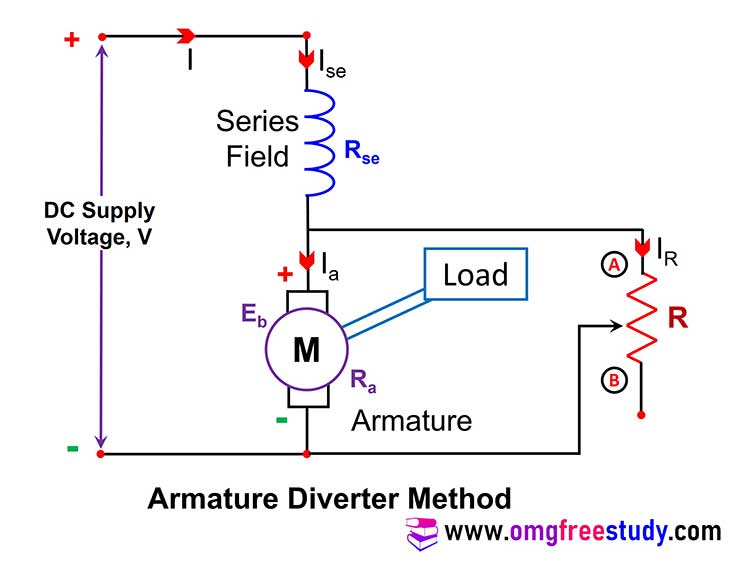
The value of resistance connected in circuit at point ‘A’ is minimum and at point ‘B’ is maximum. If sliding contact at point ‘A’ the value of resistance is minimum then current through the armature is decrease.
This will increase torque demand therefore machine will draw more current this will result increasing flux. So, field current increases hence flux increases this may results decrease in speed. Therefore at point ‘A’ speed is minimum and at point ‘B’ speed is maximum.
Tapped Field Method:
The set up for this method is as shown in fig.
The change in flux is obtained by changing the number of turns of the field winding which is in tapping position. A rotary switch is used to select the tapping as number 1, 2, 3….. etc. As we can change the selector switch position as 2, 3, 4 etc., the number of turns of field winding selection will reduce from position 1 to 6.
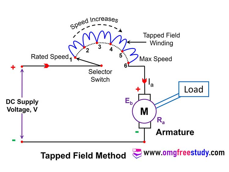
If less number of coil connected in circuit then the flux also be minimum. Hence the motor speed increases as we move selector switch form point 1 to 5.
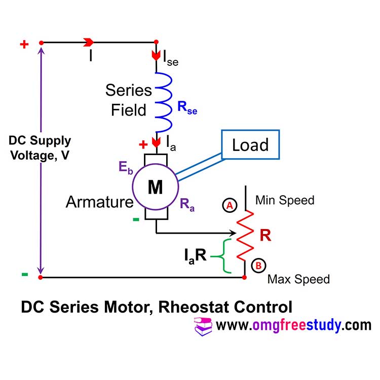
Rheostatic Control (Armature Voltage Control):
The set up for the rheostatic control of a dc series motor is shown in figure. Due to connection of the rheostat ‘R’ in series with the motor field winding and armature winding, the armature current will flow through it and there is a voltage drop of IaR across it. This result voltage across armature winding will reduce and the speed will also reduce because the speed is directly proportional to armature voltage.