By using Voltage Equation of DC motor we can find the value of back EMF and also armature current. Armature supply voltage has to overcome the opposition by Back EMF and other voltage drops such as armature voltage drop, brush drop.
Question: Write the voltage equation and power equation of DC motor.
Table of Contents
ToggleVoltage Equation of a DC Motor:
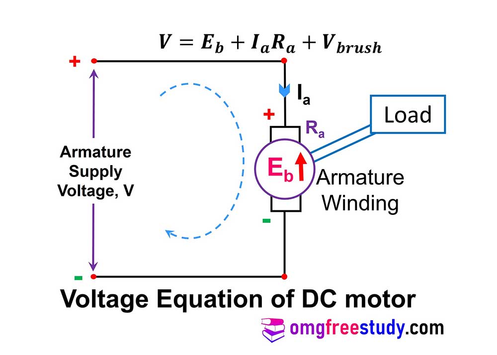
From figure we can write that,
Supply voltage = Back EMF + Voltage drop across armature + Voltage drop across Brushes
Now, mathematically express as,
But the voltage drop across brushes is negligible, so we can neglect this voltage drop.
This is the final expression for voltage and from above equation we can find out armature current (Ia) or back EMF by rearranging this equation.
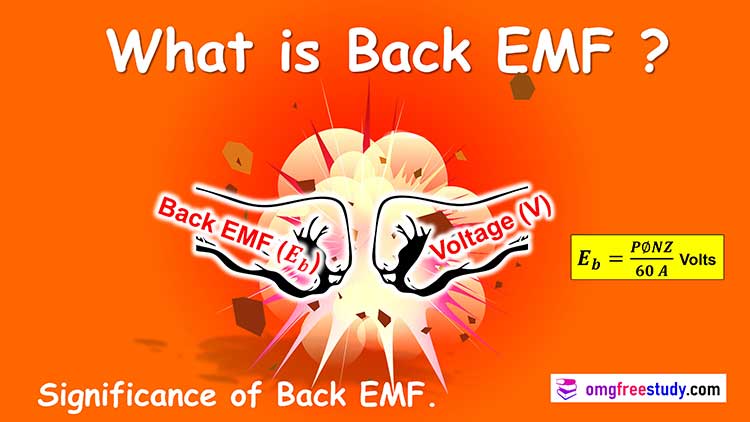
Remember that the back emf Eb is always less than the armature voltage V. i.e. Eb < V, and the difference between V and Eb is very small under all the normal operating conditions.
The Back EMF control the armature current to its normal safe value.
When mechanical load increase on motor, motor speed down. But value of back EMF is proportional to Speed of motor, so back emf also decrease. Hence value of armature current increases.
Power Equation of a DC Motor:
Let us repeat the voltage Equation of dc motor,
We know the basic equation of power i.e. P = V x I.
So we can multiply both the sides of this equation by Ia to get,
In above power equation of dc motor VIa is the electrical power supplied to the armature. On other side Eb Ia is electrical equivalent of the mechanical power produce by the dc motor. And Ia2Ra is the power loss in armature winding.
This is the final equation for power of DC motor.
You can learn more about Different type of DC motor and its application.
Working Principle of a DC Motor:
Que. State the working principle of D.C. motor.
The armature winding is connected to an external dc source, hence it plays the role of the current carrying conductor placed in the magnetic field.
Current carrying conductor placed in a magnetic field experiences a force given by equation F = B I L sinϴ, the direction of rotation which is given by Fleming’s Left Hand rule.
Where
B = external magnetic field,
I = current in conductor,
L = length of conductor in magnetic field,
ϴ = physical angle between directions of I and B.
The current carrying conductors are placed on the armature core and the field is created by the DC electromagnets around the armature to get a unidirectional motion depending on the relative directions of current and external magnetic field.
Due to the mechanical force exerted on it when placed in the magnetic field, it starts rotating.