Emergency lighting is commonly used in public buildings, workplaces, residences, etc. The main function of the emergency lamp in industry is to indicate the ESCAPE route, to provide light for passage and exit or to indicate the location of fire extinguishers.
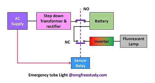
The block diagram of the emergency light is in Figure. Basic circuits without overcharging protection for battery or trickle charging facility are discussed here. Modern emergency lights have these facilities.
The AC main supply is supplied to the step down transformer as shown in the block diagram, then it is repaired to charge the battery through the sensor relay. The lamp is connected to the battery circuit by a relay. When the AC supply fails, the relay normally enables the battery in the lamp circuit connected by the closed contact and the lamp glows.
Table of Contents
ToggleEmergency Tube Light Circuit Diagram:
Emergency light attached to a normal incandescent lamp will give less light. If a fluorescent tube or LED is used in an emergency light, it will give about 3 times more light than the same wattage. So most emergency lights are included with fluorescent tube lights. The tube light requires a high voltage for its operation.
The inverter is used to convert the DC supply to AC and then amplify it to illuminate the fluorescent tube. The inverter circuit is operated by a sensor (relay). When the AC supply is not available, the battery operates a voltage inverter at the time of power failure, in which the DC is converted to AC and then reaches a high voltage to enable the fluorescent tube to light up.
Inverters are basically transistorized oscillators. They can be oscillated at a frequency of about 6.6 kHz. The frequency of the circuit can be changed by changing the values of the resistors and capacitors in the circuit connected to the base of the transistor.
When the AC supply is restarted, the sensor relay connects the battery terminals to the modified DC circuit for charging and disconnects the inverter circuit from the circuit through the relay. A suitable heat sink should be placed on the power transistor to keep the temperature of the power transistor within its temperature limit.
MCQ Questions PDF of Module 4 : Inverter and UPS
- Voltage stabilizer and UPS
- Emergency light
- Battery charger and inverter
- Stabiliser, battery charger, emergency light, inverter and UPS
- Installation of inverter in domestic wiring
Download MCQ Questions PDF of Inverter and UPS